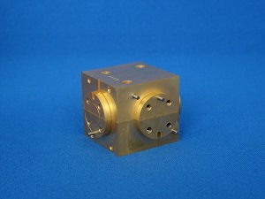
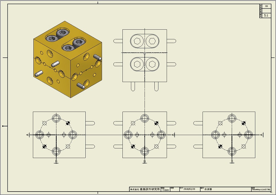
 【1×2 port】Waveguide Power Diverders
| Example of performance (WR3 , 1×2 port) | |||
|---|---|---|---|
| Min. | Typical | Max. | |
| Frequency | 220 GHz | 325 GHz | |
| Insertion loss | 0.8dB | 1.3dB | |
| VSWR | 1.2 | 1.6 | |
| Output port ratio | 0.03dB | 0.12dB | |
| ※VSWR=(10^(ReturnLoss/20))+1/(10^(ReturnLoss/20))-1 | |||
 |
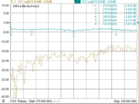 |
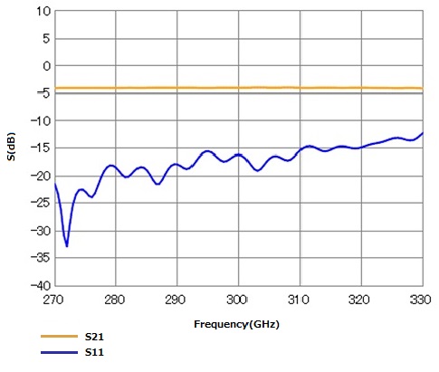
| Simulation data of Waveguide Power Diverders(WR3) | Measurement data of Waveguide Power Diverders(WR3) |
| Waveguide Size | Frequency (GHz) |
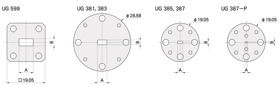
Flange | |
|---|---|---|---|
| WR | Internal Dimension(mm) A × B |
||
| WR-28 | 7.110×3.560 | 26.5 - 40.0 | UG381,UG599 |
| WR-22 | 5.690×2.850 | 33.0 - 50.5 | UG383 |
| WR-19 | 4.780×2.390 | 40.0 - 60.0 | UG383 |
| WR-15 | 3.759×1.880 | 50.5 - 75.0 | UG385 |
| WR-12 | 3.100×1.550 | 60.0 - 90.0 | UG387 |
| WR-10 | 2.540×1.270 | 75.0 - 110 | UG387 |
| WR-8 | 2.030×1.020 | 90.0 - 140 | UG387 |
| WR-6 | 1.651×0.825 | 110 - 170 | UG387P |
| WR-5 | 1.295×0.648 | 140 - 220 | UG387P |
| WR-4 | 1.092×0.546 | 170 - 260 | UG387P |
| WR-3 | 0.864×0.432 | 220 - 330 | UG387P |
| WR-2.8 | 0.711×0.356 | 260 - 400 | UG387P |
| WR-2.2 | 0.559×0.279 | 330 - 500 | UG387P |
| WR-1.5 | 0.381×0.191 | 500 - 700 | UG387P |
Waveguide Power Diverders(WR1.5 , 1×2 port)
Flange